Column setting-out is one of the early stages where architectural planning and structural detailing must describe the same building. A small error in a grid line or centre dimension can affect footing excavation, plinth beams, room sizes and the alignment of columns through the upper floors.
For this G+3 residence at Razaq Sahab Palya, Bengaluru, the drawing set moves from an architectural column placement plan to a numbered structural grid and then to the footing layout. Reading the three sheets together shows how the design information becomes usable for site marking.
The placement plan relates columns to the rooms
The column placement drawing overlays the structural member positions on the building arrangement. This helps check whether columns sit within walls, corners and practical locations without obstructing doors, circulation or important room spaces. It also shows how the stair area and the larger open portions of the plan influence the structural arrangement.
At this stage, coordination matters more than simply counting columns. Their positions should work with the architectural plan and remain consistent through the levels of the G+3 structure.
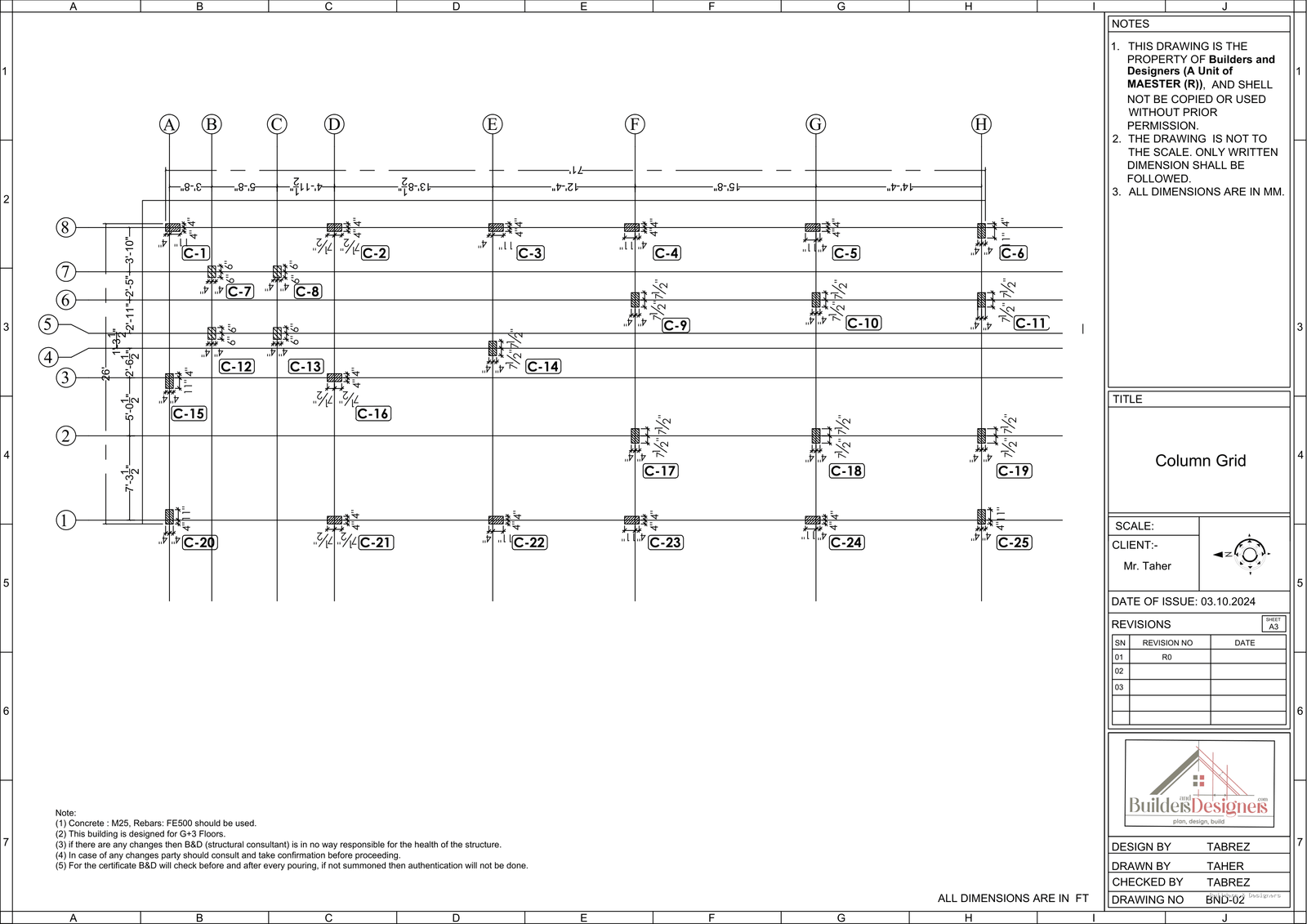
Grid references make every column identifiable
The structural grid assigns letters in one direction and numbers in the other. Columns are labelled individually, and the dimensions between grid lines provide a common reference for the drawing and the site team. Instead of locating a column from several unrelated wall dimensions, the team can refer to the intersection of known grid lines.
A good grid also makes checking easier. Overall dimensions, intermediate spacing and changes around irregular portions can be compared before excavation. The setting-out team should establish stable reference points and verify diagonal or overall measurements as required by the project survey procedure.
The same grid carries into the footing layout
The footing layout uses the same grid framework to position footing centres below the columns. This continuity is important because the footing is not located independently from the column above it. The sheet also shows footing sizes and a reinforcement schedule, but those details only work correctly when the centre positions are established accurately.
Where a footing is close to a boundary or the building outline changes, the drawing should be read carefully rather than assuming every footing is centred in the same way. Any discrepancy between site dimensions and the issued drawing needs clarification before excavation or concreting.
Practical checks before excavation
- Confirm plot boundaries and the approved building position through the required survey process.
- Establish fixed benchmarks and grid reference points that will not be disturbed during excavation.
- Check overall and intermediate grid dimensions against the latest issued drawings.
- Match column labels and centres with the footing layout.
- Verify special edge, corner and closely spaced footing conditions.
- Obtain clarification before changing any column or footing position at site.
A column grid may look like a simple set of lines, but it is the common coordinate system connecting the architectural plan, structural design and physical setting-out. Clear grids and coordinated footing drawings reduce avoidable corrections during the earliest stage of construction.